Alternator conversion wiring.
-
modelafish
- Posts: 39
- Joined: Tue Oct 08, 2019 3:33 pm
- Location: Nampa, Idaho
Alternator conversion wiring.
I've been searching for weeks, and haven't found a definitive diagram for converting my 64 Caliente 289 to an alternator. As other owners know, it has an ammeter, and everything I find (or have been given) is for a car with a generator light. They aren't wired the same ! PLUS. I don't know for sure if what I have done is working or not. Climb in the car and turn on the headlights, and the ammeter shows discharge. (so that kinda tells me it's working) Fire it up and not even a blip. And this is with the battery fully charged or not. Tried different setups. With and without a direct wire from Alt to solenoid. With and without the Stator wire. Then I put the voltmeter on the batt while running, and only shows 12.5V. Same when checking directly on the alt batt terminal. HA ! Did I have a bad rebuilt alt ? The 351C in my Model A has the same basic alt; soooo, I Swapped the alt into my Model A and fired it up. 14-15V at the battery and the alternator. Put the Model A alternator in the Comet, and 12.5V still. I'll assume for now that the alt is working, but wired wrong. But is it charging the battery ?? So does ANYONE have a definite diagram, or instructions, on converting from generator to alternator, on a 64 Comet, WITH AN AMMETER ?? (Sorry, I don't want to hear how easy a 1-wire GM alt is. I already have the parts and the budget is depleted.)
Re: Alternator conversion wiring.
Wish I could help!
Did this when I put the 351C in my 64 in the 70s but dont remember exactly what to do.
It was really simple though, think a couple of wires on the regulator were tied together and then to Alt and heavy wire
from gen to alt. I'll look at what is in my Comet now but seems to me I changed stuff when I went to the V6.
I know I was having a H of a time with this last swap till I put a good sized ground wire direct from frame to alt.
Fred
I'd rather do it myself if it's done right or not,,,isn't that what hotrodding is all about
-
Baileysvillager
- Posts: 8
- Joined: Sun May 03, 2020 1:20 pm
Re: Alternator conversion wiring.
There is a great video on Youtube that explains what needs to be done to the wiring to convert from generator to alternator . The first half of the video explains what each does. The second half is where he uses wiring diagrams to explain where the wires go and how to change them.I'm still running the gen so I haven't tried it but it looks easy. Sorry I'm not computer savvy or I would post a link but look for Moss Motors, Ltd generator to alternator conversion
-
modelafish
- Posts: 39
- Joined: Tue Oct 08, 2019 3:33 pm
- Location: Nampa, Idaho
Re: Alternator conversion wiring.
Yeah, besides the alternator to regulator ground wire, I added another one direct to the body.SASSY wrote: ↑Tue Jun 02, 2020 10:09 amWish I could help!
Did this when I put the 351C in my 64 in the 70s but dont remember exactly what to do.
It was really simple though, think a couple of wires on the regulator were tied together and then to Alt and heavy wire
from gen to alt. I'll look at what is in my Comet now but seems to me I changed stuff when I went to the V6.
I know I was having a H of a time with this last swap till I put a good sized ground wire direct from frame to alt.
Fred
-
modelafish
- Posts: 39
- Joined: Tue Oct 08, 2019 3:33 pm
- Location: Nampa, Idaho
Re: Alternator conversion wiring.
I've seen that one. (I had a TR6 for 48 years, so I'm familiar with Moss) Didn't get much from it as his diagram was for a positive ground system, and an alternator with internal regulator. I'm using a mid-60's mechanical regulator. I tried to use parts from the first years after the factory converted to alternators, with the hope that changes would be minimal.Baileysvillager wrote: ↑Tue Jun 02, 2020 11:01 amThere is a great video on Youtube that explains what needs to be done to the wiring to convert from generator to alternator . The first half of the video explains what each does. The second half is where he uses wiring diagrams to explain where the wires go and how to change them.I'm still running the gen so I haven't tried it but it looks easy. Sorry I'm not computer savvy or I would post a link but look for Moss Motors, Ltd generator to alternator conversion
Re: Alternator conversion wiring.
I still have the gen,but ,I don't have even a radio,,if I had nice stero stuff I would go to an alt,all I have is the msd ign system,but I always keep a good battery,,no cheap Wal-Mart stuff.but I have noticed it seems like the battery lasts longer then with an alt that is in other cars and trks I have....sure seems like to me....pop
pop/glenda
Re: Alternator conversion wiring.
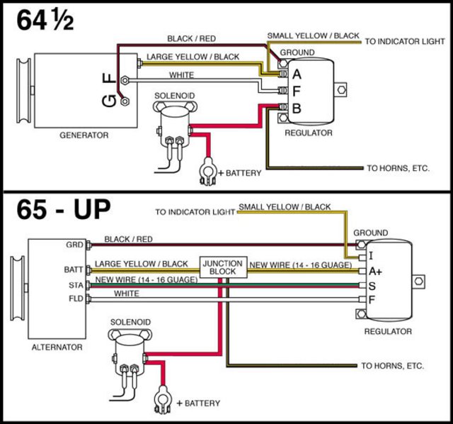
Not sure if this information is still needed but I thought I would post this just in case someone wants it.
This is for installing a Ford style alternator not a “Brand X” style.
Jim
This is for installing a Ford style alternator not a “Brand X” style.
Jim
‘64 Cyclone/ Boss 302,quads,4spd, Winters 9”
Re: Alternator conversion wiring.
Jim, do you think the alt diagram would work properly
on a 64 seeing as the yellow/black stripe wire just passes through the loop thing(tech term ) on the back of the amp gauge? Just drop the indicator light wire.
Fred
on a 64 seeing as the yellow/black stripe wire just passes through the loop thing(tech term
Fred
I'd rather do it myself if it's done right or not,,,isn't that what hotrodding is all about
Re: Alternator conversion wiring.
Fred,
I believe that my factory gauge worked after I converted to an alternator but that was over 40 years ago and I don’t remember for sure. I know now better and have a volt gauge instead of an amp gauge. My Powermaster alternator puts out 14 volts no problem. ( internal regulator)
I guess the best answer to your question is to disconnect the amp gauge ( leave it in the dash if you ant a stick looking dash) and install a volt gauge under the dash or even in the glove box.
Jim
‘64 Cyclone/ Boss 302,quads,4spd, Winters 9”
-
modelafish
- Posts: 39
- Joined: Tue Oct 08, 2019 3:33 pm
- Location: Nampa, Idaho
Re: Alternator conversion wiring.
This is what I based my original setup on. But it didn't work because of the basic difference in wiring between a gauge and a dash light. A lot of other diagrams don't even use the stator wire.
-
modelafish
- Posts: 39
- Joined: Tue Oct 08, 2019 3:33 pm
- Location: Nampa, Idaho
Re: Alternator conversion wiring.
I found this diagram for a 65 with ammeter AND alternator. Most of the wire colors didn't change much in 1 year. Followed it the best I could, and it's charging now ! Ammeter still doesn't work, but I have an idea on that as soon as I get more 10 gauge.
- 1965CometWiring with Alt and Amp.jpg (189.99 KiB) Viewed 3209 times
Re: Alternator conversion wiring.
Right on!
Hard to stop a man on a mission!
Fred
Hard to stop a man on a mission!
Fred
I'd rather do it myself if it's done right or not,,,isn't that what hotrodding is all about
-
modelafish
- Posts: 39
- Joined: Tue Oct 08, 2019 3:33 pm
- Location: Nampa, Idaho
Re: Alternator conversion wiring.
MISSION ACCOMPLISHED !! And I didn't need the extra wire. In fact, the final solution was surprisingly simple. I had initially approached it by trying to figure out how the alternator was wired. Ended up using the 65 wiring and worked backwards from the ammeter. One wire went directly to the solenoid. There was a big black wire already at the solenoid that went toward the dashboard, so leave that in place. The other side connected via a junction to the alternator and voltage regulator. Took the yellow/black that previously hooked to the generator and hooked to the batt post of the alternator. The other end ended up by the VR, along with another big black wire (that presumably came FROM the dash) and hooked both of those to the "A" terminal of the VR. The original white wire from the generator "field" connects to the alt "field" post; and the same at the VR. So no change there. The "S" post of the alt is not used, nor is the "I" post of the VR. Finally, pigtail a wire off the wire that feeds the coil to the "S" terminal of the VR to excite the alternator. It charges, and the ammeter works ! All for about $75. (and a couple of weeks of consternation looking for appropriate diagrams.) I did not use the yellow wire the 65 diagram shows going from solenoid to VR, but as I said; it works. Have not used it yet in a real world situation (i.e. driving it around,...no plates yet..) but if anything changes, I will update this post.